Thursday, July 30, 2009

Viva la difference...

Two nights ago, I cut out the "floors" for the kayak. Bascially, I took the existing pattern, traced the bottom of it and offset the inside surface by the thickness of the slats which will be the actual seating and storage surface. They extend to just inside of the chine stringers. Fairly straightforward. I opted not to use a metal bracket the way Thomas Yost does - trying to keep things from looking "industrial". Basically, I'm looking for something I think is more aesthetically appealing and easier for students to make.


On the Sea Tour 15R, the cockpit opening is between frames #3 and #4 and in Yost's boats the only slats are between the frames with the top of the slat at the bottom inside edge of the frames. I'm doing this, but also adding more slats in the area behind the seat for gear storage. These slats are primarily intended to keep gear up out of any water that may accumulate in the bottom of the boat.

Last night, I sanded the "floors" and bonded them to the frames that make up the skeleton of the boat with thickened epoxy. The hardest part was spreading an even film of epoxy. I also removed the screws that were used during the assembly process. The holes were drilled up to a larger diameter (Ø 7/32") and Ø 3/16" dowels were bonded into the holes with polyurethane adhesive. These are put in to resist shear between the stringers and the frames.


Tonight I will clean up the slats of cherry that I will use for the seating and storage surface - 1" wide slats that are 3/8" thick where the paddler sits and 1/4" thick in the rear storage area. These will be spaced approximately 3/8" apart to allow for air/water flow and a lighter boat.

I've also begun thinking about the coaming and hatch cover and am not planning on using Yost's method of plywood framing in this area. There is a definite reason for this deviation. With Yost's method, there is a frame beneath the skin. When the kayak is inverted to get water out of the boat, some of the water will be trapped by dam created by the plywood. In traditional skin-on-frame kayaks, the coaming is actually stitched to the skin and floats, for lack of a better term.

I'm still debating how I am going to accomplish what I want to with the coaming and hatch cover. My mental picture of what I want is a laminated rim like a Shaker oval box. The problem is that there were support blocks and the plywood rim which make an incredibly strong cockpit coaming in Yost's design.
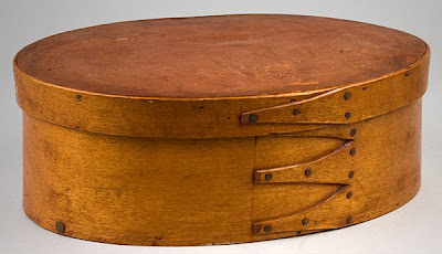

A bit more of the Thotful Spot, perhaps.

Wednesday, July 29, 2009

Monday, July 27, 2009

God? Just a minute more, please.


I can identify with Noah tonight.

Let me paint the picture for you. During dinner, we'd been listening to thunder to the north of us and watching the gathering clouds. I'm itching to get out and work on the kayak. After a day of productive, but frustrating work in the office, I just need a few minutes to keep the progress ticking along. It's just after dinnertime and we've gotten DS and DD to bed, so I head out to the garage. Call me obsessive, if you will - I prefer 'dedicated'. With the amount of rainy days that we've had this summer, any opportunity to work on the kayak is a good opportunity.

The sky isn't looking promising - it looks like it should be about 9:00 PM, but it's not yet 8:00 PM. Thunder booms in the distance. I turn on the garage lights and the outside lights and pull out the stock and tools that I need to do my work. Mosquitoes begin to gather in large numbers to join me for my task. I've got my hearing protection on as I'm working, and am using the jig saw's light (and occasional flashes of lightning in the distance) to illuminate my work. The realization that I'm standing out in a relatively open space with a grounded power tool in my hands isn't making me feel good. Dare I say, not one of my more brilliant moves, but I've only got a little bit more to do.

My work for the evening was to cut out the "floors" that will go on either side of the frames in the kayak tonight. These floors will support slats that will make up both the cockpit and the storage area behind the cockpit. Its only 6 narrow pieces of plywood - not a big job.

The flashes of lightning are coming closer together and I can now hear the thunder regardless of the hearing protection that I'm wearing. A quick check of the sky shows some truly ominous looking roiling clouds churning their way overhead as the breeze freshens from the northwest.

Please - just one more floor, one more floor...

I guess that God must look out for fools and boatbuilders. Maybe they're synonymous?

The last frame is cut and I manage to put the tools and materials back in the garage. Rain starts falling immediately after I put the sawhorses away. It's now coming down in buckets and the thunder and lightning are playing across the horizon outside the window. In the nick of time.

Saturday, July 25, 2009

And a bit more progress...


Thursday evening, I managed to glue the majority of the frame together. Today, I took a bit of time to put the bow and stern together. Thomas Yost doesn't detail the shapes of the bow and stern. He gives instruction, but doesn't give profiles. I can't understand why this level of detail isn't in the plans, but I followed his instructions and this is what I finished up with at the bow:


While I'm not obsessing about the weight of the but, I added some holes to the stem and stern forms. I think they'll be fine structurally. At this point in the build, the weight of the frame is about 16 - 1/2 pounds. Floors, coaming, an access hatch and the skin are yet to be installed.


After I cut the first stern pattern, I decided that I wanted a slightly more plumb stern profile and re-made a new cardboard pattern. The picture above shows the result after tracing the cardboard onto the plywood and mounting it. I still have to remove the screws that were used to fixture the stringers to the frame and install the dowels that will prevent the stringers from breaking loose in shear.

There are a few things that I'm a bit uncertain about - the center stringer comes a bit low at the tip is one. This may or may not be intentional because of the skinning of the hull, and it may not matter at all.

Not bad after about 8 hours of work.

Wednesday, July 22, 2009

Tuesday, July 21, 2009

Tech Tip Tuesday


I don't know if any of you recall (or will admit) to having watched Magnum PI during the '80's. In the series, the lead character; Thomas Magnum who was played by Tom Sellick, used the narrative gimmick of his "little voice". The "little voice" would warn him when something wasn't quite right.

Well, I have that little voice in my head and you probably do, too. Last night as I was trying to align frames, my little voice said, "You're working way too hard at this." I had installed the sheer stringers and the frames and was starting to install the chine stringers. Every time that I put one in place, the frames would shift, and I couldn't be assured that the frames hadn't moved axially, or if they were vertical or square to the centerline of the kayak. I started to feel that things weren't going well and rather than make an irretrievable mistake, I retreated to my thotful spot. I mulled things for a while and then decided to sleep on things.

When you are boatbuilding, it should be fun. If it's not fun, you should be thinking about working smarter, not harder. Think about a new method. Do some research. Ask questions of someone else who has experience doing what you're doing.

In my case, after mulling things over, the "duh" moment came to me. I was thinking about the mounting of forms 1 and 6. I needed something to hold the rest of the frames in position, but I didn't need something that permenant - as a matter of fact, I don't want something that permenant. My big concern was that I could keep the forms vertical, perpendicular to the centerline and in position axially. One problem was that whatever I came up with couldn't obstruct the keel stringer that would be along the centerline. I also will need to be able to extract the supports after assembling all the stringers.

Here's the solution. It's a simple plywood cross - made from 3/4" thick plywood that slots together (tightly). The center of the cross is offset to allow clearance for the keel stringer. The horizontal member fits between the sheer and chine stringers. At the bottom of the cross is a piece of 2x2 that will allow the plywood cross to be mounted to the strongback. Here's one of the 4 that I made this evening.


It's not square, because it doesn't need to be - I'm only concerned that the surface that meets the floor is a flat. Tomorrow we find out if I out-smarted myself.

Monday, July 20, 2009

Some Progress


I managed to get my forms cut out of the Occume plywood. My friend got her forms cut out as well and took them home to sand and finish. This is a fairly straightforward process. We tried to approaches to cut the outer profile - a jig saw with a 20 TPI blade and a bandsaw. In lots of regards, I think the jigsaw was actually easier than the bandsaw as we lacked the throat depth on a 14" bandsaw to get at all of the features without using the jigsaw to finish. We used a 3/4" Forstener bit to clean out the corners on the inside and to allow us to start the cut on the inside of the frame where we used a jigsaw regardless of how we cut the outer profile.

After the forms were cut out, I took a 1/8" radius round-over bit in a palm router to ease the inside edges of the forms. I figure I don't want sharp corners where it may touch either the paddler or dry bags to avoid chafing and potential punctures. It will also help the finishing process. I also eased the sharp corners between the stringer notches with a little sandpaper. This is the end result.


I used the same 1/8" radius roundover bit to radius the corners of the stringers. Again, to keep from having sharp corners in contact with both the paddler and the Dacron skin that will cover the boat.

We also constructed two strongbacks - relatively simple - a 12' 2x4 for the top plate and another 8' 2x4 set on edge and screwed to the top plate to keep it from warping. On the top surface, the form locations were marked out. The two end mounts (rectangular pieces with a vertical slot in yesterday's post) were attached to the top of the beam using 2x4 blocks. It is important to remember that the forms are spaced to the same side, so one of the end mounts has to be offset by the thickness of the form stock - in this case 1/2". Here's one end of the strongback.


The strongback was placed on sawhorses and the form 1 and 6 were attached to the end mounts at the proper height, leveled from side-to side and clamped in place. Once this was done, the sheer stringers were installed using bungee cords. I was suspicious of the reason for bungees instead of clamps, but the bungess let the stringers slide. This isn't apparent unto the next step. Extra hands or clamps, however, are good for holding the stringers in place until you can put the bungees on. Unless you are an octopus, this is not easy. Here are forms 1 and 6 with the sheer stringers in place.


This next step is really made easy by this next tool - a Quick Grip clamp/spreader which when set up as a spreader will push the stringers apart so that you can install form 3 in between the stringers. It's a great tool.


The next step is to install the forms between the stringers and ensure that they are vertical, perpendicular to the centerline and at their correct spacing. Not that difficult really. Once this has been done, mark the stringers on either side of the form. After that is done, the chine stringers and the keel stringer are installed. Once I tried this, I had some issues I'll talk about later. Time to retreat to my thotful spot.


Well, at least there was a little progress this evening - not much, but a little.